Precision alignment, solid engineering, and razor thin tolerances. These are all things that are necessary when attaching an electric motor directly to the drive train of a car. With its higher torque, our AC-50 would be able to pull the car to speed from a standstill with a direct connection to the wheels entirely bypassing the transmission. This would be an elegant solution but it requires the aforementioned things; precision alignment, solid engineering, and razor thin tolerances. It just so happens these are all things I am very bad at. So instead we decided to take the easier (and more common) solution. Adapt the electric motor to the existing transmission of the car. This makes the process similar to just swapping engines.
Motor to transmission coupling is pretty common in EV conversions. It has many benefits over the alternative (motor to drive train) including being much easier to do and maintaining the existing shifting of the car. While the motor could pull the car to speed driving directly to the wheels, it will accelerate MUCH faster if you shift through the gears the way you would with a gas engine. This was the way we decided to go when we started planning.
Three basic components are required: the motor, the transmission adapter plate, and the flywheel adapter coupler thing (that’s the technical term).
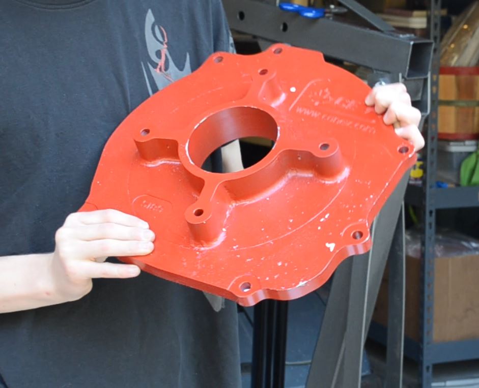 The bright red transmission adapter plate ready to be bolted to the motor!
Essentially, the motor shaft goes into the flywheel adapter which then bolts into the flywheel where the old motor would have. The flywheel then connects to the rest of the transmission assembly in the same fashion it would have with the original setup. The transmission adapter then bolts to the outer casing of the motor and the bell housing of the transmission to keep everything held together nicely.
The adapter plate is just a big piece of machined aluminum that bolts to the motor and then to the transmission. It had to go on first and it was trivial to put on; just four bolts and some washers. The adapter plates job is simply to help out the motor mounts and ensure that the motor doesn’t move around relative to the transmission.
The flywheel is also essential to all of this. It, with the help of its friends the clutch and release plates, serves to transfer all of the power coming from the motor into the rest of the drive train. It is important that the flywheel is weighted perfectly so as not to oscillate or cause unwanted vibrations as the motor revs. Because of the nature of a rotary engine the old flywheel was weighted to compensate for the momentum generated by the drum of the motor. Our electric motor doesn’t generate any momentum as it rotates smoothly around a static axis. This means the compensating weight on the flywheel will actually cause oscillation instead of preventing it. So all that struggle of liberating it from the motor? Wasn’t necessary.
But now we have a really cool flywheel trophy from the original engine! Anyhow, we ended up having to order a new unweighted (often called sport) flywheel. Not only was this flywheel much lighter (Yay, better gas mileage! Oh, wait...), more importantly it was not weighted. These lightened sport flywheels are designed to have the counterweight added on to them as a separate piece and we just didn’t do that. Problem solved.
The flywheel coupler thing has those coveted razor thin tolerances. In fact, it’s tolerances are thinner than a razor. Quite a bit thinner. In order to fit it around the shaft of the motor we had to heat it with a heat gun to expand the metal enough to pound it on with a rubber mallet. Yes, believe it or not, this is the way its designed to be put on. Then it was a simple matter of bolting the flywheel onto the adapter and the clutch plate and pressure plate to the flywheel in turn. Then the whole assembly was ready to be attached to the transmission.
Here is where it got difficult. Imagine threading a needle but you can't see the head of the needle or the string. And the needle weighs 150 pounds. That’s what it was like installing the motor/flywheel/clutch/adapter assembly into the transmission. It took a good hour or so of fiddling to finally get the teeth of the coupler to mesh with the teeth on the input shaft of the transmission. It is best described with a video.
The first shot of this video is just the flywheel mounted to the coupler on the motor, then the rest of the clutch assembly installed onto it ready to be put in the transmission.
After that though it was finished! It was a simple matter of bolting the transmission adapter plate to the transmission bell housing with provided bolts and the install was finished! Or at least we hope it is. We have no way of testing or seeing whether everything has set correctly because the bellhousing is sealed once the adapter plate is bolted in. We’ll just have to wait until the rest of the components are in to give it a spin but that comes later.
So there you have it! Motor installed, right? Well, we still need to attach it to the existing motor mounts. As it is it is resting on a two-by-four between the mounts, obviously not a very permanent solution. Spoilers: we already made the motor mount I am really late writing this post. I’ll have a post up about that process soon.
Thanks for reading!